What is IoT based car parking system?
Hi everyone! Welcome to an another blog of My Tech Studio. Today we will learn how to make IOT based car parking system using arduino and NodeMCU (ESP 8266) Wi-Fi module and blink application. With the help of a NodeMCU (ESP 8266) and mobile application the parking system can be monitored from anywhere around the world. In this blog you will also learn how to use the tapes and LED widgets in blink application this is the second version of the car parking monitoring system while in the first version. I designed a computer application and vb.net for monitoring the parking slots. So let's get started.
What type of sensors are used in smart parking?
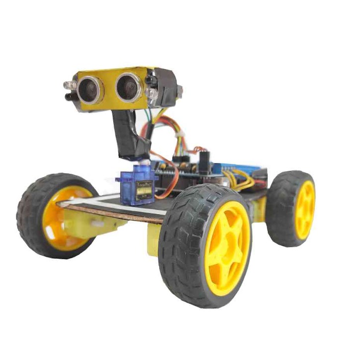
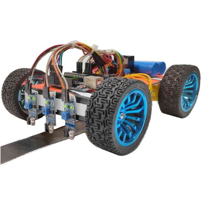
The components that are required for making this project are - Arduino, NodeMCU Wi-Fi module, six infrared sensors. I modified this circuit and aided only NodeMCU (ESP 8266) Wi-Fi module and a power supply.

Smart Parking system using nodemcu -
In NodeMCU module of TX and RX pins all connected with pin number two and pin three of the Arduino. While the VIN pin of Arduino is directly connected with the output of the voltage regulator. This is a regulated 5 volt power supply based on lm7805 a voltage regulator to the 470 micro farad capacitors are connected at the input and output side of the regulator with a 330 ohm resistor is connected in series with a 2.5 volt LED. This is a counter limiting resistor while this is a DC female socket over here you can connect a 12 volt adopter of poetry. But you can also power up the NodeMCU using your laptop’s USB port. Here I'll be using two USB cables. One of the cable will be used for powering up the Arduino and the other USB cable will be used to power up the NodeMCU module. First of all open the blink application and then click on the new project option. The project name a sparking if you want you can set any other name also. Click on the choose device and select NodeMCU and make sure that you have set the connection type to Wi-Fi click on the create button an authentication token will be sent on your Gmail ID. Now this is the authentication token simply copy and paste it in your programming click on the screen and search for the de Bridget you change names to walking one and walking to you now. You can see we have two tapes barking one and barking to each barking we'll have three slots for the slots. We can use the led widget when the desired tab is selected. Click on the screen and search for the led widget you if I click on a slot one as you can see I have used the virtual pen v10. Now click on the 3d Sid the name is slow to click on the pin and select V 11 follow the same steps for slot 3.

How IoT is used in smart parking system?
I followed the same exact steps for parking too and assigned a virtual pins to each slot our basic application designing is completed now let's discuss the programming in this project we are using two sketches a one for the Arduino and the other one for the NodeMCU (ESP 8266) Wi-Fi module. So first let's discuss the Arduino programming. We start with his includes software serial dot H. That means this is a pre-processor directive and thought which means that this is a header file so with the help of this you can make multiple serial ports so let's define a serial port with the name Node MCU on pin number two and pin number three of the Arduino Sofia serial ignored him Cu 2 comma 3 pin number 2 is the aurochs and pin number 3 is the TX, then I defined pins for the 6 infrared sensors connected with pins 4 to 9 then defined six variables of the type string see data is a variable of the type string and it will be used to store the complete message consisting of the sensors values as you know more friends every Arduino and mega program has at least two functions which are the wide set up and wide loop functions what means that this function is not returning any value and the empty parentheses means that this function is not taking any arguments is the input serial dot begin 9600 activates the serial communication and 9600 is the portrait this will be used for the debugging purposes node MCU toad begin 9600 activates the serial communication with Node MCU which is connected with pin number 2 and the pin number 3 of the heart. We know pin mode is a function and it takes two arguments is the input the pin number open name and the status which can be input or output.

All the senses are set to input thence thoughts a while loop function these are six user-defined functions and each function is used to monitor the infrared sensor these are the calling functions each function is executed a one by one and check the status of the infrared sensor whether there is a car in front of the sensor or not then we make a complete message consisting of values of all the senses these values are separated using the comma is a delimiter serial dot println C data this instruction is used to send the complete message to the serial monitor for the debugging purposes Node MCU dot println C data this instruction is used to send the complete message to the node MCU module then there is a delay of 6 seconds and finally we empty the seeded a variable for the new data white B 1 slot 1 parking 1 slot 1 this is a user-defined function this function has two F conditions if digital read parking 1 slot 1 ire sensor equals low if car is present in front of the sensor then sensor 1 equals 255 store 255 and sensor 1 if digital read parking 1 slot 1 IR sensor equals high if no car is present in front of the sensor then sensor 1 equals 0 store 0 in sensor 1 similarly the remaining functions all the functions are exactly the same.
Code for smart parking system -
Now let's discuss the Node MCU programming. Before you start the programming first of all make sure that you download all the necessary libraries and you installed the Node MCU board and you also install a driver for the USB to UART. This is the authentication number which was send via email. I simply copied and pasted it over here. This is the name of your Wi-Fi and this is the password then defined some variables of the type string character and integer this function since are the nose-up time every second to virtual pin. One in the Abe widgets reading frequency should be set to push this means that you define how often to send data to blank application serial dot begin 9600 activates serial communication when 9600 is the baud rate these are the six user-defined functions which are executed every second which I will discuss in a minute if serial dot available equals equal 0 if Node MCU. Mario hasn't received any data from the Arduino and then simply keep executing these two functions. If serial dot available greater than 0 if no times you module has received data and simply read the serial port and add each character with my strength to make a complete message this condition makes sure that the entire message is received the entire message which is received is split using the gate value function which is a user-defined function each sensor value is stored in a variables. l am P and Q then we simply convert these strengths to integers and add and we empty the variable for new data since the value 1 is a user-defined function and is used to send the value stored and LED 1 to the virtual pen 10 using the bling dot virtual write function and similarly the sense of value to function is used to send the AVD to value to the world - open 11 and so on for the remaining functions gate value is a user-defined function and it takes three arguments, which is the input data separator and the index this function is used to split the above string messages using comma is the delimiter. That’s all for today. Hope this blog is helpful for you.