What is a Line follower robot?
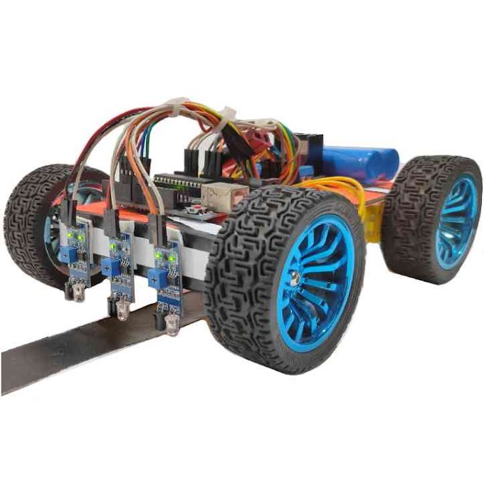
Line follower robot is another example of arduino project. The name “Line follower robot” suggest a robot which can follow the line. In other words the path of the line or track is become the path of the robot. A line follower robot is an automation related project where we use the arduino and some other sensors (IR sensor) to automate the car.
Which sensor is used in line follower robot?
Infrared (IR) sensor is used in line follower robot. The basic work of a line follower robot is to follow the line. And this can be done by using IR sensors. You can use any number of IR sensors to build your robot. But it is always preferable to use three or four IR sensors to build the robot. Even you can use seven or eight IR sensors in your project. But you have to use minimum two IR sensors for making a line follower robot.
Where are line follower robot used?
Line follower robot is used in industries to automate the functionality. A line follower robot is used to carry goods from one place to another with in the industries. Line follower robot will follow the track that is allocated to it and reached to its destinations. It will reduce the need of man power in any industry.
How do you make a line follower robot?
Line follower robot is one of the easiest arduino project. In this post I will cover all the related topics about a line follower robot. Also I will tell you every important steps for building a line follower robot. Mainly I cover four main topics which are –
(1) How to build the structure of a line follower robot
(2) How to build the circuit of a line follower robot
(3) How to write down the code in line follower robot
(4) How to calibrate the IR sensors of line follower robot
Components –
(1) DC Geared Motor
(2) Arduino uno
(3) L298N Motor Driver
(4) IR Sensor
(5) Jumper Wire
(6) 12 Volt Lipo Battery
Structure Making –
The basic structure of a line follower robot is quite similar to any arduino car. The only thing that differs is the placement of the IR sensors in front of the robot. So while building a line follower robot you have to keep your attention in the front part of the robot. And you have to keep enough space for the installation of the IR sensors. At first you have to take the four dc geared motor for your robot. Connect the wires in the motor. Then you have to take a wooden or plastic board which can be used as a chassis of the robot. Fix all the dc geared motor in the four corners of the chassis by using the glue.
Now it’s time to connect the wheels in the dc motors. But before this you may use the shaft coupling for the better performance of the robot. Now you have to connect the wheels in the motors. Use the screw and fix them properly with the shaft of the dc motors. This is the basic configuration of the line follower robot.
Circuit Connection –
Now we have to make the circuit for line follower robot. And for this purpose you need some circuit component like Arduino uno, L298N motor driver and IR sensors. At first take the L298N motor driver and place it in the rear side of the chessis. Then take the wires of the dc motor and connect it with the output terminal of the L298N motor driver. After this take the Arduino uno, and then place it in front of the motor driver. At this time you have to build the connections between the arduino and L298N motor driver. For this you may follow the steps.
Connection between Arduino and L298N motor driver –
(1) ENA of motor driver – D5 of Arduino uno
(2) IN1 of motor driver – D6 of Arduino uno
(3) IN2 of motor driver – D7 of Arduino uno
(4) IN3 of motor driver – D8 of Arduino uno
(5) IN4 of motor driver – D9 of Arduino uno
(6) ENB of motor driver – D10 of Arduino uno
After all this connections you have to take the IR sensors. Then you have to do the connections between IR sensor and Arduino uno.
Connection between IR sensor and Arduino –
(1) Output pin of 1st IR sensor – A2 pin of Arduino
(2) Output pin of 2nd IR sensor – A1 pin of Arduino
(3) Output pin of 3rd IR sensor – A0 pin of Arduino
These are all the connections. For better understand you can follow the circuit diagram –
Also you have to give the 5 volt positive supply to all the IR sensors and the motor driver. At last you have to give the power supply to the circuit. You can use a 12 volt Lipo battery to power up the circuit. This is all about the circuit connection. Now you have to move to the coding section.
Arduino Code –
Now you have to do the coding for line follower robot. In this project we use three IR sensor. So our code will be based on this three IR sensors. Connect the arduino with your computer and do the coding.
Line follower robot working principal –
(1) When the left ir sensor detect the black line, the robot will move to left.
(2) When the right ir sensor detect the black line, the robot will move to right.
(3) When the middle ir sensor detect the black line, the robot will go forward.
(4) When all the ir sensor detect the black line, the robot will stop.
For better understand you can follow this code –
// Line Follower Robot
int S_A = 5; //speed motor a
int M_A1 = 6; //motor a = +
int M_A2 = 7; //motor a = -
int M_B1 = 8; //motor b = -
int M_B2 = 9; //motor b = +
int S_B = 10; //speed motor b
int R_S = A0; //sincer R
int S_S = A1; //sincer S
int L_S = A2; //sincer L
void setup()
{
pinMode(M_B1, OUTPUT);
pinMode(M_B2, OUTPUT);
pinMode(M_A1, OUTPUT);
pinMode(M_A2, OUTPUT);
pinMode(S_B, OUTPUT);
pinMode(S_A, OUTPUT);
pinMode(L_S, INPUT);
pinMode(S_S, INPUT);
pinMode(R_S, INPUT);
analogWrite(S_A, 230);
analogWrite(S_B, 230);
delay(200);
}
void loop()
{
if ((digitalRead(L_S) == 0)&&(digitalRead(S_S) ==1)&&(digitalRead(R_S) == 0)){forword();}
if ((digitalRead(L_S) == 1)&&(digitalRead(S_S) == 1)&&(digitalRead(R_S) == 0)){SturnLeft();}
if ((digitalRead(L_S) == 1)&&(digitalRead(S_S) ==0)&&(digitalRead(R_S) == 0)) {turnLeft();}
if ((digitalRead(L_S) ==0)&&(digitalRead(S_S) == 1)&&(digitalRead(R_S) == 1)){SturnRight();}
if ((digitalRead(L_S) == 0)&&(digitalRead(S_S) == 0)&&(digitalRead(R_S) == 1)){turnRight();}
if ((digitalRead(L_S) == 1)&&(digitalRead(S_S) == 1)&&(digitalRead(R_S) == 1)){Stop();}
}
void forword(){
digitalWrite(M_A1, HIGH);
digitalWrite(M_A2, LOW);
digitalWrite(M_B1, HIGH);
digitalWrite(M_B2, LOW);
}
void SturnRight(){
digitalWrite(M_A1, LOW);
digitalWrite(M_A2, HIGH);
digitalWrite(M_B1, HIGH);
digitalWrite(M_B2, LOW);
}
void turnRight(){
digitalWrite(M_A1, LOW);
digitalWrite(M_A2, LOW);
digitalWrite(M_B1, HIGH);
digitalWrite(M_B2, LOW);
}
void SturnLeft(){
digitalWrite(M_A1, HIGH);
digitalWrite(M_A2, LOW);
digitalWrite(M_B1, LOW);
digitalWrite(M_B2, HIGH);
}
void turnLeft(){
digitalWrite(M_A1, HIGH);
digitalWrite(M_A2, LOW);
digitalWrite(M_B1, LOW);
digitalWrite(M_B2, LOW);
}
void Stop(){
digitalWrite(M_A1, LOW);
digitalWrite(M_A2, LOW);
digitalWrite(M_B1, LOW);
digitalWrite(M_B2, LOW);
}
After the coding you have to upload the code in arduino. Select the correct port and board type and then upload it to the arduino. Here we come to the end of coding section.
IR sensor calibration –
Now it is the time to test the robot. Place the robot in a track and observe its performance. If you notice that the robot is not working properly, then you have to calibrate the ir sensors. Change the value of potentiometer in the ir sensors and try it once. If the result is not satisfactory, you have to change the value of potentiometer again. In this manner you have to find the right value of potentiometer. And the line follower robot will working properly without any error.


